


OFF

MIKROE-3144
31 g
Status:
LTE IoT 2 Click is a compact add-on board that allows connection to the LTE networks. This board features the BG96, a LTE module from Quectel. It offers two LTE technologies for M2M communication and the Internet of Things (IoT). This module is an embedded IoT communication solution that supports the LTE Cat M1 and NB1 technologies, offering an alternative to similar Low Power Wide Area Network (LPWAN) solutions, such as the ones provided by Sigfox and LoRa. It also offers various features, allowing simple and reliable connection to these new 3GPP IoT technologies. This Click board™ makes the perfect solution for many M2M applications, such as smart metering in various industries (agriculture, gas distribution, water distribution), product tracking, and more.
LTE IoT 2 Click is supported by a mikroSDK compliant library, which includes functions that simplify software development. This Click board™ comes as a fully tested product, ready to be used on a system equipped with the mikroBUS™ socket.
This product is no longer in stock
Availability date:
LTE IoT 2 Click is based on the BG96, an LTE module from Quectel Wireless Solutions that supports LTE CAT M1 and NB1 technologies developed with IoT applications in mind. In addition, it supports EGPRS at 850/900/1800/1900 MHz, meaning that it can be used globally; it is not restricted to any region. The BG96 consists of several internal blocks or sections, such as the RF section, NAND flash and DDR RAM section, the Power Management section, and the cellular baseband processor with the peripheral interfaces. The support for the Cat M1 and NB1 technologies and the ultra-low power consumption make this module a perfect choice for the forthcoming 3GPP IoT technology.
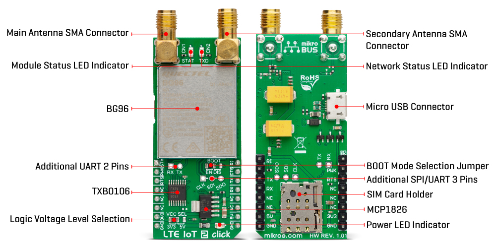
LTE IoT 2 Click supports several peripheral interfaces, including USB, UART, SIM card, I2C, SPI, I2S, and GPIO. The main UART interface (UART 1) supports baud rates of 9600, 19200, 38400, 57600, 115200, 230400, 460800, 921600, and 3000000 bps, with the default setting to 115200bps. This interface is used for data transmission and exchanging AT communication commands with the host MCU. Besides the main UART, there are two more auxiliary UART interfaces, one of which is shared with the SPI interface (UART 3/SPI), while the other is used for debugging purposes (UART 2). All the additional UART/SPI interfaces are available on the Click board™ in the form of unpopulated headers, with the pads clearly labeled (RX, TX for the UART debug interface header, and CLK, SDI, SDO for the SPI interface header).
The Quectel BG96 module has to be powered by a clean and stable power supply. The voltage needed for the module to work properly is about 4V, and it is derived from the 5V mikroBUS™ rail through the MCP1826, a 1A low drop output (LDO) regulator from Microchip. Although the Quectel BG96 module is an ultra-low power device, the cellular network modules, in general, are notorious for their high power consumption while actively exchanging data, so 1A LDO had to be used. Digital sections of the BG96 are supplied by 1.8V, so it is necessary to condition the incoming communication bus lines that connect the host MCU with the module. Using its internal LDO regulator, the BG96 module provides the needed reference voltage for one side of the TXB0106, a 6-bit bidirectional level shifter and voltage translator. The reference voltage for the other side of the TXB0106 level shifter is taken from the onboard SMD jumper, labeled as VCC SEL. This jumper selects between 3.3V and 5V from the mikroBUS™, depending on the used MCU type and its logic voltage level requirements.
The BG96 module is designed as the traditional DCE device (Data Communication Equipment), offering the full serial interface pin count, including the hardware flow control pins (CTS, RTS). These pins are routed to the mikroBUS™ CS (RTS) and the INT pin (CTS) and can be used in the MCU software if hardware flow control is needed. The RI pin is the ringing indicator routed to the mikroBUS™ PWM pin. The STAT pin is used to signal the status of the device. This pin is routed to the mikroBUS™ AN pin through the level shifter, and the yellow LED labeled STAT is used to indicate the device status visually. The network status is indicated by the red TXD LED located next to the STAT LED. The PWRKEY pin is routed to the mikroBUS™ RST pin. A LOW pulse on this pin will toggle the device's power status. If powered down and the valid power supply voltage is present, a pulse on this pin will power up the device. The STAT LED, and the STAT (AN) pin will indicate the successful action.
LTE IoT 2 Click has an SMD jumper labeled as the BOOT, which forces the device to boot from the USB. It can be used during firmware development or for firmware updates. During normal operation, the USB BOOT mode is disabled. This Click board™ is also equipped with a micro USB connector that allows the module to be powered and configured by a personal computer. The Nano SIM card holder on the back of the Click board™ is used to install a micro SIM card. This device cannot be used without a valid SIM card, which allows connection to the cellular network. Both 1.8V and 3V SIM card types are supported. In addition, two SMA antenna connectors are used to connect the appropriate antennas: a main antenna SMA connector and a secondary (GNSS) antenna SMA connector. The main antenna connects the module to the LTE base station.
LTE IoT 2 Click can be used with a GSM/GPRS antenna, such as the Rubber GSM/GPRS Antenna right angle, found in our shop. The secondary global positioning (GNSS) antenna can be of both active or passive types since the connector offers a power supply from the internal LDO of the BG96 (1.8V). The module supports several global positioning technologies, including GPS, GLONASS, BeiDou/Compass, Galileo and QZSS.
This Click board™ can operate with either 3.3V or 5V logic voltage levels selected via the VCC SEL jumper. This way, both 3.3V and 5V capable MCUs can use the communication lines properly. Also, this Click board™ comes equipped with a library containing easy-to-use functions and an example code that can be used as a reference for further development.
Type
GPS/GNSS,LTE IoT
Applications
Can be used for smart metering, IoT networking, remote monitoring automation and control (RMAC), and other IoT / M2M applications which rely on a cellular network connection
On-board modules
BGE96 - LTE CAT M1 / NB1 / EGPRS module from Quectel
Key Features
Embedded TCP/UDP/PPP stack, CAT NB and CAT M1 technologies support, enabled for all regions, aimed at M2M and IoT applications, dual SMA antenna connectors, USB connectivity, visual network and status indication, and more
Interface
UART,USB
ClickID
No
Compatibility
mikroBUS™
Click board size
L (57.15 x 25.4 mm)
Input Voltage
3.3V or 5V
This table shows how the pinout on LTE IoT 2 click corresponds to the pinout on the mikroBUS™ socket (the latter shown in the two middle columns).
| Notes | Pin | Pin | Notes | ||||
|---|---|---|---|---|---|---|---|
| Module status | STA | 1 | AN | PWM | 16 | RI | Ring Indicator |
| Module Power-Up | PWK | 2 | RST | INT | 15 | CTS | UART CTS |
| UART RTS | RTS | 3 | CS | RX | 14 | TX | UART TX |
| NC | 4 | SCK | TX | 13 | RX | UART RX | |
| NC | 5 | MISO | SCL | 12 | NC | ||
| NC | 6 | MOSI | SDA | 11 | NC | ||
| Power supply | 3.3V | 7 | 3.3V | 5V | 10 | 5V | Power supply |
| Ground | GND | 8 | GND | GND | 9 | GND | Ground |
| Label | Name | Default | Description |
|---|---|---|---|
| PWR | - | - | Power LED indicator |
| LD2 | TXD | - | Network status LED indicator |
| LD3 | STAT | - | Module status LED indicator |
| JP1 | BOOT | Left | Boot Mode Selection EN/DIS: Left position EN, Right position DIS |
| JP2 | VCC SEL | Left | Logic Voltage Level Selection 3V3/5V: Left position 3V3, Right position 5V |
| Description | Min | Typ | Max | Unit |
|---|---|---|---|---|
| Supply Voltage | 3.3 | - | 5 | V |
| Operating Frequency Range | 850 | - | 1900 | MHz |
| Data Rate | - | - | 375 | kbps |
| Output Power | - | - | +23 | dBm |
We provide a library for the LTE IoT 2 Click as well as a demo application (example), developed using MIKROE compilers. The demo can run on all the main MIKROE development boards.
Package can be downloaded/installed directly from NECTO Studio Package Manager(recommended), downloaded from our LibStock™ or found on Mikroe github account.
Library Description
This library contains API for LTE IoT 2 Click driver.
Key functions
Send command function with parameter.
LTE IoT 2 send SMS in PDU mode.
Generic parser function.
Example Description
This example reads and processes data from LTE IoT 2 click.
void application_task ( void )
{
if ( app_connection_status == WAIT_FOR_CONNECTION )
{
// CGATT - request IMSI
lteiot2_send_cmd_check( <eiot2, LTEIOT2_CMD_CGATT );
app_error_flag = lteiot2_rsp_check( );
lteiot2_error_check( app_error_flag );
Delay_ms( 500 );
// CREG - network registration status
lteiot2_send_cmd_check( <eiot2, LTEIOT2_CMD_CREG );
app_error_flag = lteiot2_rsp_check( );
lteiot2_error_check( app_error_flag );
Delay_ms( 500 );
// CSQ - signal quality
lteiot2_send_cmd( <eiot2, LTEIOT2_CMD_CSQ );
app_error_flag = lteiot2_rsp_check( );
lteiot2_error_check( app_error_flag );
Delay_ms( 5000 );
}
else
{
log_info( &logger, "CONNECTED TO NETWORK" );
// SMS message format - PDU mode
lteiot2_send_cmd_with_parameter( <eiot2, LTEIOT2_CMD_CMGF, "0" );
app_error_flag = lteiot2_rsp_check( );
lteiot2_error_check( app_error_flag );
Delay_ms( 3000 );
for( ; ; )
{
// Get GPS info
gps_parser_flag = 1;
lteiot2_send_cmd_with_parameter( <eiot2, LTEIOT2_CMD_QGPSGNMEA, ""GGA"" );
app_error_flag = lteiot2_rsp_check( );
lteiot2_error_check( app_error_flag );
Delay_ms( 3000 );
if ( gps_parser_flag == 0 )
{
log_printf( &logger, "> Sending message to phone number...rn" );
lteiot2_send_sms_pdu ( <eiot2, SIM_SMSC, PHONE_NUMBER_TO_MESSAGE, gps_info_message );
app_error_flag = lteiot2_rsp_check( );
lteiot2_error_check( app_error_flag );
Delay_ms( 10000 );
Delay_ms( 10000 );
Delay_ms( 10000 );
}
}
}
}
The full application code, and ready to use projects can be installed directly from NECTO Studio Package Manager(recommended), downloaded from our LibStock™ or found on Mikroe github account.
Other Mikroe Libraries used in the example:
Additional notes and informations
Depending on the development board you are using, you may need USB UART click, USB UART 2 Click or RS232 Click to connect to your PC, for development systems with no UART to USB interface available on the board. UART terminal is available in all MIKROE compilers.
This Click board™ is supported with mikroSDK - MIKROE Software Development Kit. To ensure proper operation of mikroSDK compliant Click board™ demo applications, mikroSDK should be downloaded from the LibStock and installed for the compiler you are using.
For more information about mikroSDK, visit the official page.
NOTE: Please be advised that any peripheral devices or accessories shown connected to the Click board™ are not included in the package. Check their availability in our shop or in the YMAN section below.

$889.00

$11.00

$79.00

$449.00

$299.00

$29.00

$29.00

$5.49

$3.00

$99.00

$349.00

$299.00

$449.00

$349.00

$349.00

$269.00

$249.00

$209.00
