


Hi folks i hope u can help me this has been realy busting my head for ages now
im trying to make my 12f683 sense a voltage drop anything under 2.8v then then apply pulses at whatever set time from there. After it detects the voltage drop it would do nothing for 500us, then drive the pin on the PIC Hi for 500us every 'x' number of ms/sec (like 1ms) so it would go Read wait 500us Hi 500us wait 8ms Hi 500us wait 8ms Hi 500us and that should put the pulses on time
my codeings not the best so i need some help plz this is what ive got so far
unsigned line2;
void main() {
    ANSEL = 4; // Make A2 Pin Analog
    GPIO = 0; // Initilize GPIO PORT
    CMCON0 = 7; // Turn off Comparators
    TRISIO = 0; // MAKE GPIO AS OUTPUT
    GPIO.F2 = 1; // set pin GP2 as input
    ADCON0 = 1;
    do { // beginning of line read
        line2 = Adc_Read(2); // Read AN2 channel
        if (line2<1500);
        {
        // output_high(GPIO.F2);
        }
    } while (1); // endless loop (as this condition is always satisfied)
}//~
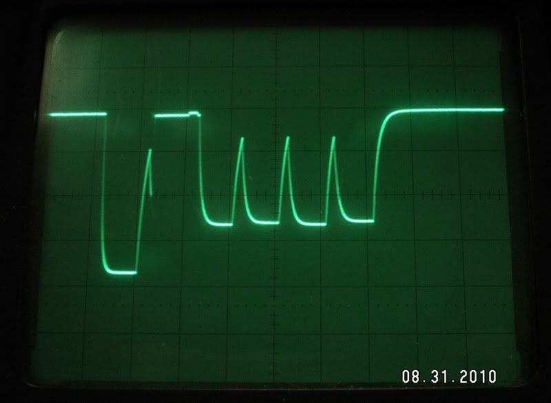
Please check the attached pictures of the oscilloscope reading im trying to detect
100 of these pulses happen every second and thats what im trying to detect
hope you can help me out thanks for your time
12F683 Sensing ADC change and Loop Help :-( Loosing sleep
12F683 Sensing ADC change and Loop Help :-( Loosing sleep
- Attachments
-
- This is when its stabe and nothings pressed
- notpressed.jpg (34.92 KiB) Viewed 6896 times
-
- This is when its fully pressed
- fullypressed.jpg (35.56 KiB) Viewed 6896 times
-
steve42lawson
- Posts: 183
- Joined: 06 Mar 2008 17:35
- Location: St. George, UT
- Contact:
Re: 12F683 Sensing ADC change and Loop Help :-( Loosing slee
Hi RADMiller,
First, it would really help if you would put your code inside code tags (i.e. or use the "Code" button, above) so it looks like this:
Much easier to see what's going on 
As for the problem, perhaps it's the line where you intend to make pin GP2 an input [GPIO.F2 = 1;] (thank you for the comment, BTW ). The proper way to do that is: TRISIO.F2 = 1; or TRISIO.B2 = 1; as I like to do it. Thus your code becomes:
Note: I always use 'B' instead of 'F' for bit designators (e.g. GPIO.B2) because those are defined in the def file (e.g. C:\Program Files\Mikroelektronika\mikroC PRO for PIC\defs\P12F683.c). Probably just a superstition 
If this doesn't solve your problem, then I would need you to explain the situation a little better:
First, it would really help if you would put your code inside code tags (i.e.
or use the "Code" button, above) so it looks like this:Code: Select all
unsigned line2;
void main() {
ANSEL = 4; // Make A2 Pin Analog
GPIO = 0; // Initilize GPIO PORT
CMCON0 = 7; // Turn off Comparators
TRISIO = 0; // MAKE GPIO AS OUTPUT
GPIO.F2 = 1; // set pin GP2 as input
ADCON0 = 1;
do { // beginning of line read
line2 = Adc_Read(2); // Read AN2 channel
if (line2<1500);
{
// output_high(GPIO.F2);
}
} while (1); // endless loop (as this condition is always satisfied)
}//~
As for the problem, perhaps it's the line where you intend to make pin GP2 an input [GPIO.F2 = 1;] (thank you for the comment, BTW
Code: Select all
unsigned line2;
void main() {
    ANSEL = 4; // Make A2 Pin Analog
    GPIO = 0; // Initilize GPIO PORT
    CMCON0 = 7; // Turn off Comparators
    TRISIO = 0; // MAKE GPIO AS OUTPUT
    TRISIO.B2 = 1; // set pin GP2 as input
    ADCON0 = 1;
    do { // beginning of line read

        line2 = Adc_Read(2); // Read AN2 channel
        if (line2<1500);
        {
        // output_high(GPIO.F2);
        }

    } while (1); // endless loop (as this condition is always satisfied)
}//~
If this doesn't solve your problem, then I would need you to explain the situation a little better:
- You didn't explain what "pressed" means and how it relates -- my guess: pressed and not pressed is what alters the condition that you are testing for ("under 2.8 Volts"). The scope-shots show a max P-P voltage of 2.76, but I can't tell if there is a DC component that would push that above 2.8 V (I'm not familiar with the scope you are using, so not able to fully decipher the markings)
- So I don't have to look up the 12F683, include things like number of bits of ADC resolution your intending. I'm guessing 10 bits, in which case 1500 seems out of range (1024 would be the max, right?)
- Tell us how your code is behaving now (what is it doing, or not doing). That could help in pin pointing the problem.
- Imagine you are me and think about what I might need to know in order to help you
Humility is the lack of the desire to impress, not the lack of being impressive.
Re: 12F683 Sensing ADC change and Loop Help :-( Loosing slee
Thanks for your reply. ahh i didnt realise thats how get your code like that. The scope isnt mine its some 1 thats helping me also as i dont have 1.
Ok its a controller im trying to control with the chip i need to sense when a certain button is pressed and then make it goto a loop untill the button isnt pressed. ive included another pic that will help u understand more i think.
All the buttons use the same line that sensis wich button is pressed the R2 button always stays low ish im trying to control the R1 button
- Attachments
-
- PS3COM2CloseLabeled.jpg (35.12 KiB) Viewed 6856 times
-
steve42lawson
- Posts: 183
- Joined: 06 Mar 2008 17:35
- Location: St. George, UT
- Contact:
Re: 12F683 Sensing ADC change and Loop Help :-( Loosing slee
OK, I took a deeper look at your code and noticed that
ADCON0 = 1;
selects ADC channel 0, yet you set up A2 as the analog input. Try:
ADCON0 = 0b00001101; // I always do it this way because it's easier for me to see -- I leave it to you to do the conversion to decimal
Thus the code would become (with my previous correction included):
If that doesn't do it, then please include the following in your next post:
Please answer my question about the ADC resolution (10 bits or what) and why you're comparing it to 1500.
Also, what does "R2 button always stays low ish im trying to control the R1 button" mean [please proofread your posts before sending]?
Also, some kind of schematic would help.
In other words, you're asking for my [our?] help. Please don't make me [us?] have to work any harder, to help you, than I [we?] need to. I have my own projects I'm working on, and to have to dig for information (like ADC resolution, scope metrics, design specifics), and decipher your descriptions, makes me reluctant to proceed.
ADCON0 = 1;
selects ADC channel 0, yet you set up A2 as the analog input. Try:
ADCON0 = 0b00001101; // I always do it this way because it's easier for me to see -- I leave it to you to do the conversion to decimal
Thus the code would become (with my previous correction included):
Code: Select all
unsigned line2;
void main() {
    ANSEL = 4; // Make A2 Pin Analog
    GPIO = 0; // Initilize GPIO PORT
    CMCON0 = 7; // Turn off Comparators
    TRISIO = 0; // MAKE GPIO AS OUTPUT
    TRISIO.B2 = 1; // set pin GP2 as input
    ADCON0 = 0b00001101;
    do { // beginning of line read
        line2 = Adc_Read(2); // Read AN2 channel
        if (line2<1500);
        {
        // output_high(GPIO.F2);
        }
    } while (1); // endless loop (as this condition is always satisfied)
}//~
Please answer my question about the ADC resolution (10 bits or what) and why you're comparing it to 1500.
Also, what does "R2 button always stays low ish im trying to control the R1 button" mean [please proofread your posts before sending]?
Also, some kind of schematic would help.
In other words, you're asking for my [our?] help. Please don't make me [us?] have to work any harder, to help you, than I [we?] need to. I have my own projects I'm working on, and to have to dig for information (like ADC resolution, scope metrics, design specifics), and decipher your descriptions, makes me reluctant to proceed.
Humility is the lack of the desire to impress, not the lack of being impressive.
Re: 12F683 Sensing ADC change and Loop Help :-( Loosing slee
Hi sorry m8t im new to all this fourm stuff.
R2 is an actual button on the controller so are X [] O ^ and R1 is the button that i want to controll if you check first image of the controller pcb i need would solder the GP2 Pin to the R Common point on the board as this is were the readings are from
please take a look at these other readings they wer taken from a Fluke Scopemeter 97 Taken buy RDC this is an analog scope.
The controller looks for the pulses to be driven Lower than they are sitting at default. The third picture is with no buttons on the controller pressed. The R2 Button is lower already is by design and how the controller is setup. The second picture is the R1 button pressed
what im trying to do here is force the button R1 Lo pulse back Hi 'x' number of times per second after it's pressed, but only that pulse. Forcing the entire line Hi 'x'n/s will do this, but it has the negative side effect of doing it to every button on the controller not just the one that you want.
the A/D is 10bit that's 0-1023 steps with 0 being 0v and 1023 being 2.8v.
im sorry if im not the best at trying to explain whats happining i realy apreashiate your help thanks
- Attachments
-
- Controller PCB (R COMMON is where GP2 would be connected)
- ps3pcb.jpg (85.69 KiB) Viewed 6836 times
-
- R1 button pressed only
- COM2R1-1.jpg (86.59 KiB) Viewed 6836 times
-
- no buttons on the controller pressed
- COM2Default.jpg (83.36 KiB) Viewed 6836 times
-
steve42lawson
- Posts: 183
- Joined: 06 Mar 2008 17:35
- Location: St. George, UT
- Contact:
Re: 12F683 Sensing ADC change and Loop Help :-( Loosing slee
Geeze, it's like pulling teeth...
OK, first of all, just so I'm not making assumptions -- you tried the two code "corrections" and that didn't solve it, right? Did it change ANYTHING? Did it improve the situation or make it worse (a little feedback, please).
Another cursory look at your code raises more questions:
1. You're reading the voltage on the same pin as you are using to drive the line high? If so, you need to do two TRISIO changes: TRISIO.B2 = 1 to make it an input, and TRISIO.B2 = 0 to make it an output.
2. You still haven't answered my question about the value 1500. As you corroborated, the range at 10 bits is 0 - 1024 so why 1500?!?
3. Why is the line output_high(GPIO.F2); commented out? Is that on oversight?
Also, it would help to know how it (originally) was NOT working -- i.e. how it's MIS-behaving. Have you looked at what is going on at pin GP2 with the scope? Have you done this with that pin disconnected from the PCB to see if there is any activity? Have you tried simulating the conditions with, say a resistor and a variable voltage source to see if you can run the voltage down and have the PIC react to the change?
Humility is the lack of the desire to impress, not the lack of being impressive.
Re: 12F683 Sensing ADC change and Loop Help :-( Loosing slee
I'm wondering if you're measuring your signal with the proper reference. If I'm understanding the situation correctly you're trying to detect a switch closure and then have the PIC do something. Is that correct? If so, I would think the signal would go to a solid low state for as long as the button is pressed. I'm seeing pulses while R1 is (assuming) closed. What's the power supply voltage? 3.3 or 5 vdc?
Best Regards,
Wayne
Wayne
-
steve42lawson
- Posts: 183
- Joined: 06 Mar 2008 17:35
- Location: St. George, UT
- Contact:
Re: 12F683 Sensing ADC change and Loop Help :-( Loosing slee
Another thought: This application is very time critical, and (why am I not surprised) you haven't mentioned the clock speed you are using. Also, possible pertinent information would be if you are using a crystal or internal RC or what. In fact, if you want to give a full picture, include all of the config bit settings.
Sorry if I sound POed but it's a little frustrating how much information you withhold (or leave out). Once again, think like YOU are the one trying to help you, and think about what YOU might need to help solve the problem. Take a little time to go over your post, reread my questions, make sure you've answered them all, and then consider what else might be helpful. Make sure you have given me some feedback regarding the effectiveness (or lack) of my previous attempt at helping you.
To your credit, though, the scope shots are awesome, and help a lot -- thanks for that.
Take a little time, so you spare a little of MY time
Humility is the lack of the desire to impress, not the lack of being impressive.
Re: 12F683 Sensing ADC change and Loop Help :-( Loosing slee
Hey all,
This whole mess is for a PS3 controller to rapid fire a button, but only one specific button at a time by controlling the Common line of the controller instead of just driving the actual button line Hi/Lo or connecting the 2 sides of the button together with some kind of switch like is typically done.
The buttons on the PS3 controllers are all 'pressure sensitve', ie Analog, and don't work a thing like most other controllers where they are just driven Hi or Lo or in some Matrix layout. The PS3 controller has a few Common lines, 1 for the left side (COM1) of the controller, one for the right side (COM2) and one for the middle (COM3), for what is being attempted here COM2 is the main focus.
Just for the record, I know Jack and spit about coding, and Jack left town. Maybe enough in Basic to get a blinking LED out of a wet paper bag, but that's about it, and figure I only understand half of how this controller is actually working, which is all just fine with me as there's nothing wrong with learning something new. Also, I could give 2 shakes less about R/F on gaming controllers, it's not my thing at all and people that use them online should be flogged. If you want to play around in single player or irritate your friends with it that's all good, but as soon as you take it public, you're a tool, period. I'm after the challenge of knowing how this is done, it has been twice already now that I know of, and that's what interests me about this.
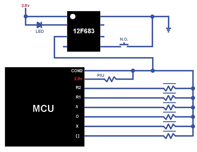
This is a VERY cheesy schematic of the COM2 line and all of it's buttons. The P/U is a Pull Up, and the Resistors with lines over them are the buttons, where the harder they are pressed the lower the Resistance value and why they are Analog. The COM2 line seems to be the Input in this case, so it's kinda bass ackwards of what one is normally used to.
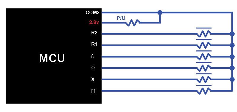
The above scope shots aren't really that accurate and no timing and such was really given, so hopefully these should clear all of that up. Also the buttons aren't driven exactly to Ground, doing that on purpose causes them all to freak out, so not exactly sure how to classify that part of it now other than they are driven lower than where the 2.8v Pull Up brings them to.
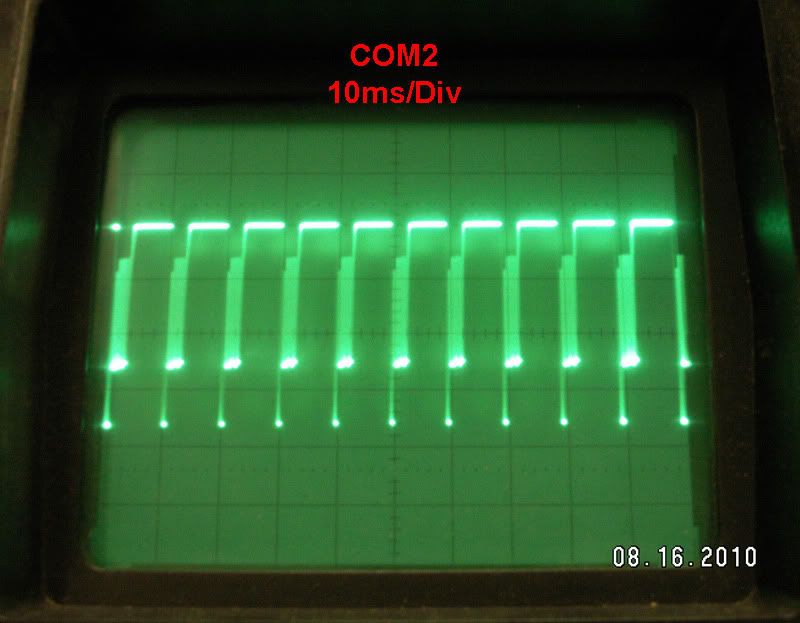
The scope being used is 60MHz and 500mV/DIV for all measurements here.
Scoping the COM2 line will get you this 100Hz signal, shown at 10ms/DIV, 2ms and finally 0.5ms
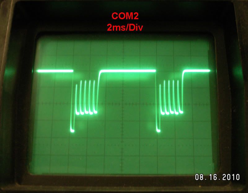
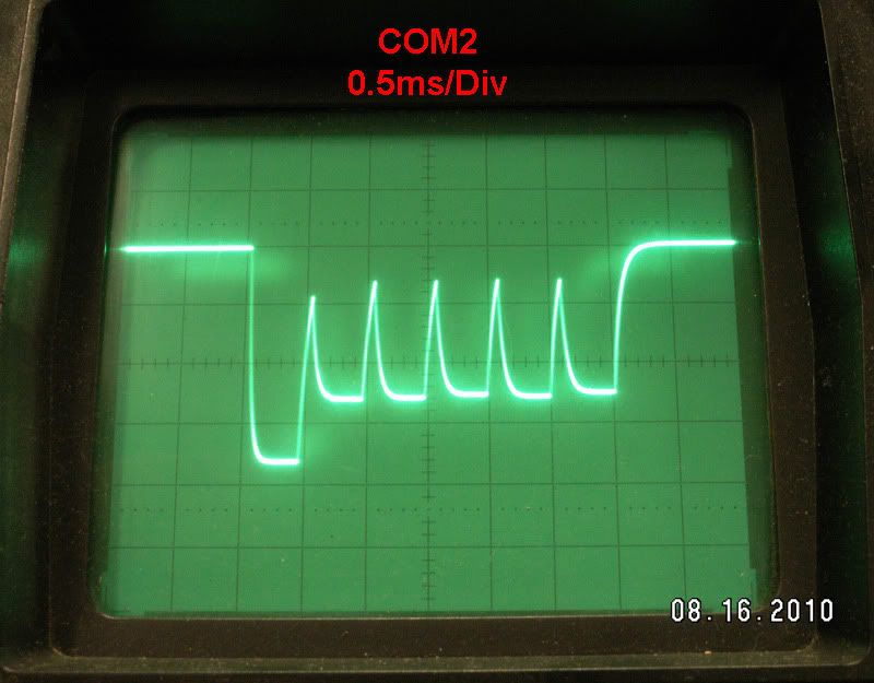
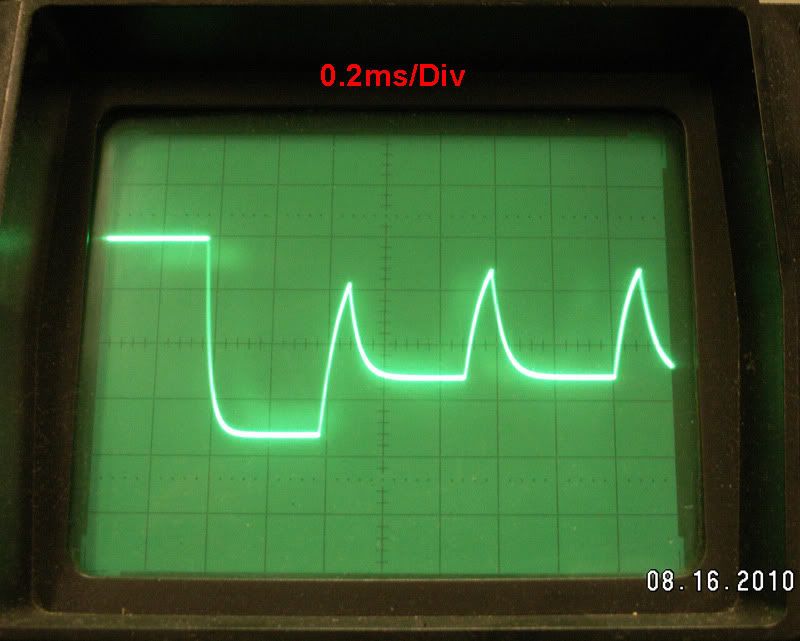
In the last pic there you can see all 6 of the buttons, from left to right they are R2, R1, /\, O, X and [ ]. R2 is lower because it's button Resistor is a lower value than the rest.
This is at 0.2ms/DIV for a closer look.
Scoping just the R1 line will get you this..
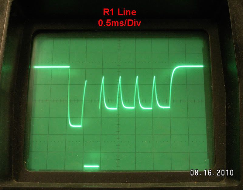
..and that stays constant no matter what button it pressed and how hard, what does change though is the COM2 line.
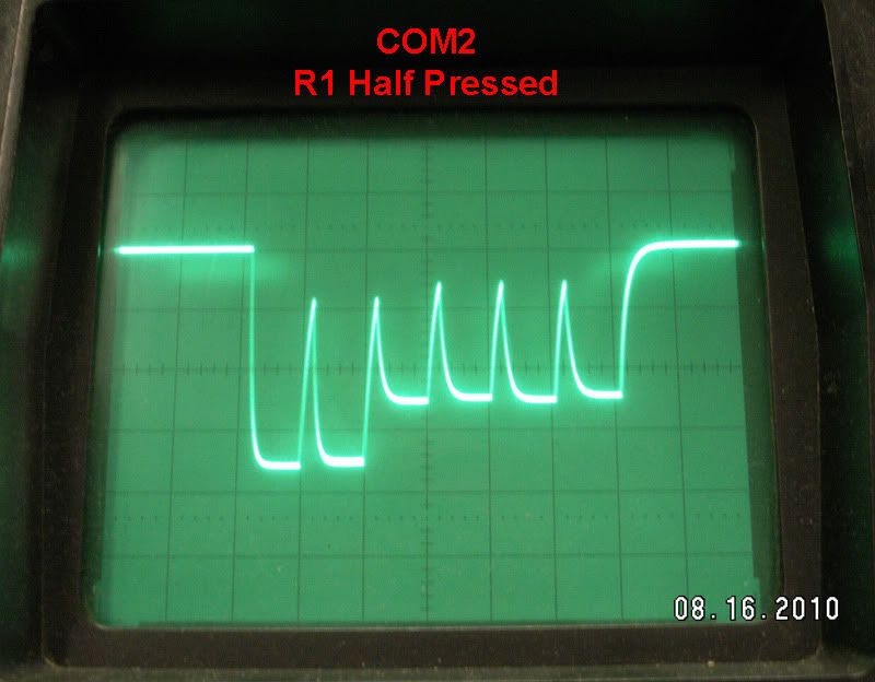
This is the COM2 line with the R1 button pressed around Half way..
..and then pressed all the way..
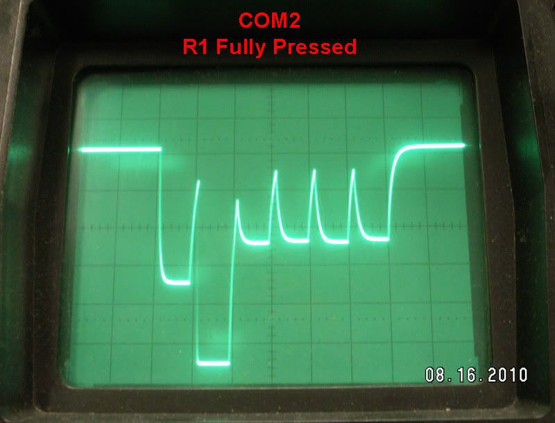
You can see that with it pressed all the way it looks just like the R1 line. Those are not the same pic labeled differently, the R1 line stays like it is, COM2 is what varies.
One could easily enough use a PIC or whatever with a Transistor or switch IC and connect the R1 and COM2 lines together to make the button press, or possibly even drive the R1 line Hi 'x' number of times per ms for the desired R/F effect, but that would only work on the R1 line and that's it. The goal of this is to use ONLY the COM2 line to do whichever button is desired, just happens to be R1 in this case though if it's figured out the option to do any other or combination thereof shouldn't be to hard to add in the mix.
The chosen PIC is a 12F683, some internal OSC and aside from that it's all up in the air as to exactly how to go about 'watching' and then 'altering' this COM2 signal. I know that the one pin used to connect to COM2 is the GP4/AN3/T1G/OSC2/CLKOUT pin of the 683, but I've no idea if they're using the Analog function, the Timer1 Gate or what the deal there is.
Aside from that the only other things that are connected to the PIC are Vdd (same 2.8v as the Pull Up) Vss, an LED on GP5 and then a N.O. switch on GP2 to change R/F modes, which isn't important right now, just getting the R1 button to pulse when pressed, without affecting any of the other buttons, is all that's after to start with. Once that's done it's just a matter of timing after that and then the bells and whistles can be added in.
So somehow this..
..can be setup to detect when only the R1 (or any other button) is pressed, and then drive just that one button's 500us drop in the signal back Hi without messing up any of the others.
I've no idea if the falling edge is being detected and then wait 500us to 'skip' R2, pulse R1 hi for 500 us and then wait 2ms for the other buttons to pass and start all over or how this is being done, or the best way to go about it, if I did I wouldn't be posting. Just wanted to show the hardware side of things in as much detail as possible and see if that helps out with this any.
This whole mess is for a PS3 controller to rapid fire a button, but only one specific button at a time by controlling the Common line of the controller instead of just driving the actual button line Hi/Lo or connecting the 2 sides of the button together with some kind of switch like is typically done.
The buttons on the PS3 controllers are all 'pressure sensitve', ie Analog, and don't work a thing like most other controllers where they are just driven Hi or Lo or in some Matrix layout. The PS3 controller has a few Common lines, 1 for the left side (COM1) of the controller, one for the right side (COM2) and one for the middle (COM3), for what is being attempted here COM2 is the main focus.
Just for the record, I know Jack and spit about coding, and Jack left town. Maybe enough in Basic to get a blinking LED out of a wet paper bag, but that's about it, and figure I only understand half of how this controller is actually working, which is all just fine with me as there's nothing wrong with learning something new. Also, I could give 2 shakes less about R/F on gaming controllers, it's not my thing at all and people that use them online should be flogged. If you want to play around in single player or irritate your friends with it that's all good, but as soon as you take it public, you're a tool, period. I'm after the challenge of knowing how this is done, it has been twice already now that I know of, and that's what interests me about this.
This is a VERY cheesy schematic of the COM2 line and all of it's buttons. The P/U is a Pull Up, and the Resistors with lines over them are the buttons, where the harder they are pressed the lower the Resistance value and why they are Analog. The COM2 line seems to be the Input in this case, so it's kinda bass ackwards of what one is normally used to.
The above scope shots aren't really that accurate and no timing and such was really given, so hopefully these should clear all of that up. Also the buttons aren't driven exactly to Ground, doing that on purpose causes them all to freak out, so not exactly sure how to classify that part of it now other than they are driven lower than where the 2.8v Pull Up brings them to.
The scope being used is 60MHz and 500mV/DIV for all measurements here.
Scoping the COM2 line will get you this 100Hz signal, shown at 10ms/DIV, 2ms and finally 0.5ms
In the last pic there you can see all 6 of the buttons, from left to right they are R2, R1, /\, O, X and [ ]. R2 is lower because it's button Resistor is a lower value than the rest.
This is at 0.2ms/DIV for a closer look.
Scoping just the R1 line will get you this..
..and that stays constant no matter what button it pressed and how hard, what does change though is the COM2 line.
This is the COM2 line with the R1 button pressed around Half way..
..and then pressed all the way..
You can see that with it pressed all the way it looks just like the R1 line. Those are not the same pic labeled differently, the R1 line stays like it is, COM2 is what varies.
One could easily enough use a PIC or whatever with a Transistor or switch IC and connect the R1 and COM2 lines together to make the button press, or possibly even drive the R1 line Hi 'x' number of times per ms for the desired R/F effect, but that would only work on the R1 line and that's it. The goal of this is to use ONLY the COM2 line to do whichever button is desired, just happens to be R1 in this case though if it's figured out the option to do any other or combination thereof shouldn't be to hard to add in the mix.
The chosen PIC is a 12F683, some internal OSC and aside from that it's all up in the air as to exactly how to go about 'watching' and then 'altering' this COM2 signal. I know that the one pin used to connect to COM2 is the GP4/AN3/T1G/OSC2/CLKOUT pin of the 683, but I've no idea if they're using the Analog function, the Timer1 Gate or what the deal there is.
Aside from that the only other things that are connected to the PIC are Vdd (same 2.8v as the Pull Up) Vss, an LED on GP5 and then a N.O. switch on GP2 to change R/F modes, which isn't important right now, just getting the R1 button to pulse when pressed, without affecting any of the other buttons, is all that's after to start with. Once that's done it's just a matter of timing after that and then the bells and whistles can be added in.
So somehow this..
..can be setup to detect when only the R1 (or any other button) is pressed, and then drive just that one button's 500us drop in the signal back Hi without messing up any of the others.
I've no idea if the falling edge is being detected and then wait 500us to 'skip' R2, pulse R1 hi for 500 us and then wait 2ms for the other buttons to pass and start all over or how this is being done, or the best way to go about it, if I did I wouldn't be posting.
Screwing up is one of the best learning tools, so long as the only thing you're not learning is how to screw up.
-
steve42lawson
- Posts: 183
- Joined: 06 Mar 2008 17:35
- Location: St. George, UT
- Contact:
Re: 12F683 Sensing ADC change and Loop Help :-( Loosing slee
Use the comparator to monitor the COM2 line. Set CVref to a voltage just above the R2 pulse minimum voltage (so the other pulses don't trigger it) and use the interrupt to synchronize the timing and generate a pulse coincident with the pulse position of the function you want to control. Since the comparator will change state on the falling edge of the R2 pulse, you can, probably, affect it too.
By "generate a pulse" I mean, change the GP4 line from a input to an output (using TRISIO), write a 0 to it (to pull it low), and around 400us later, change it back to an input (so it goes to a hi-impedance state and thus no longer affects the COM2 line.
I looked back at your code and noticed that you're calling "output_high". It seems to me, that should be "output_low" (or is your oscilloscope upside down)?
Humility is the lack of the desire to impress, not the lack of being impressive.
Re: 12F683 Sensing ADC change and Loop Help :-( Loosing slee
Each button 'pulse' lasts for 500us, and pulsing it Lo wouldn't do any good as that's what pressing the button does to cause it to fire, it needs to be driven Hi to 'mask' it so many times per second, this way the controller only counts the Lo pulses that are 'let thru'.
What needs to happen is..
Wait for the start of the falling edge (pin set as input or whatever) then wait 450us to 500us to 'skip' over R2, change to output and set Hi for 500us, back to TRIS and wait 3ms to skip the rest of the buttons, then start all over again. This would keep the R1 button from working completely, which would be a good start, then after that it's just a matter of timing the Hi pulses so only so many of them happen at such and such a time, thus creating the R/F on the button.
I can't code (which you'll see here in a second) but I've been tinkering off and on with this thing for awhile now, but have no idea how to use the INT, CCP and probably less than half of the ADC stuff, which from what I understand can be used to do this, but the 500us pulse just jumps all over the place how I have it setup, it doesn't 'sit' in the R1 spot like it should.
To everyone that gets a good laugh from that, or doesn't understand it at all, again, not a coder, but I would like to know what I'm doing wrong here if anyone can see it, aside from trying to code for this that is. I'm sure it's not starting off just right on the falling edge, and that throws the rest of it all off time, but again if I knew what I was doing I'd have it done already and no more headache from trying to figure it out.
What needs to happen is..
Wait for the start of the falling edge (pin set as input or whatever) then wait 450us to 500us to 'skip' over R2, change to output and set Hi for 500us, back to TRIS and wait 3ms to skip the rest of the buttons, then start all over again. This would keep the R1 button from working completely, which would be a good start, then after that it's just a matter of timing the Hi pulses so only so many of them happen at such and such a time, thus creating the R/F on the button.
I can't code (which you'll see here in a second) but I've been tinkering off and on with this thing for awhile now, but have no idea how to use the INT, CCP and probably less than half of the ADC stuff, which from what I understand can be used to do this, but the 500us pulse just jumps all over the place how I have it setup, it doesn't 'sit' in the R1 spot like it should.
Code: Select all
#chip 12F683, 4                  'PIC12F683 run at 4MHz
#config WDT=OFF, MCLRE=OFF, OSC=INTRCIO, PWRT=ON


TRISIO = b'00011000'
ANSEL = b'00011000'               'Fosc/8, AN3 Analog
ADCON0 = 1


#define COM2  GPIO.4              'COM2


Dim FE as word                    'Dimension FallingEdge as word (10 bit)


main:

	FE = ReadAD10(3)                    ' Read AN3 line and see what the value is
	If (FE = 900) then                  ' if value is lower than 900
	wait 450 us	                      ' wait 450 us to skip over R2
	end if
	out                                 ' call Sub to set pin as output
	COM2 = 1                            ' set pin Hi
	wait 500 us                         ' for 500us
	tri                                 ' call Sub to set pin back to input
	wait 3 ms                           ' wait 3 ms to skip the rest of the buttons
	goto main                           ' repeat

return
END


sub out
 TRISIO = 0
 CMCON0 = 7
end sub


sub tri
 TRISIO = b'00011000'
end sub
Screwing up is one of the best learning tools, so long as the only thing you're not learning is how to screw up.
-
steve42lawson
- Posts: 183
- Joined: 06 Mar 2008 17:35
- Location: St. George, UT
- Contact:
Re: 12F683 Sensing ADC change and Loop Help :-( Loosing slee
Try this:
Note: I added a 'Less Than' to your IF statement, and I moved the 'end if' to the bottom of the code block that pulses the COM2 pin. The reasoning being:
Code: Select all
main:

   FE = ReadAD10(3)                    ' Read AN3 line and see what the value is
   If (FE <= 900) then                  ' if value is lower than 900
   wait 450 us                         ' wait 450 us to skip over R2
   out                                 ' call Sub to set pin as output
   COM2 = 1                            ' set pin Hi
   wait 500 us                         ' for 500us
   tri                                 ' call Sub to set pin back to input
   wait 3 ms                           ' wait 3 ms to skip the rest of the buttons
   end if
   goto main                           ' repeat

return
END
- 1. Rarely will the value be exactly 900. You want to catch cases where it is lower than 900, right?
- 2. Only when the value is 900 or below do you want the code block, that generates the pulse, to execute. The way you have it, it is only waiting 450 us whenever the ADC returns a value of 900, and it is ALWAYS generating the pulse, no matter WHAT the ADC is returning
Humility is the lack of the desire to impress, not the lack of being impressive.
Re: 12F683 Sensing ADC change and Loop Help :-( Loosing slee
Thanks steve42lawson, though I've already tried that. It works the exact same both ways, equals was just the last way I tried it since less than wasn't cutting it.
What I figure I'm not doing right is polling the pin for the change, and then starting the code. Catching the falling edge as soon as possible is the key to this mess, and I'm sure my code there isn't doing that at all.
What I figure I'm not doing right is polling the pin for the change, and then starting the code. Catching the falling edge as soon as possible is the key to this mess, and I'm sure my code there isn't doing that at all.
Screwing up is one of the best learning tools, so long as the only thing you're not learning is how to screw up.
Re: 12F683 Sensing ADC change and Loop Help :-( Loosing slee
Think I got it, had to add in too not start the code if the value wasn't under what I picked, but could swear that I tried this before as well and it didn't work, but it seems too now.
Just need to tweak some timing and test it in game so make sure the R1 button isn't recognized, but the scope shows it's hitting in roughly the right spot now, finally.
EDIT: Confirmed it does disable R1 in game now and doesn't change how any of the other buttons work.
Code: Select all
	FE = ReadAD10(3)                ' Read AN3 line and see what the value is
	If (FE <= 1010) then            ' if value is lower or equal to 1000 then go for it
	else if (FE >= 1011) then       ' if not then
	goto main                       ' repeat until it is
	end if
EDIT: Confirmed it does disable R1 in game now and doesn't change how any of the other buttons work.
Screwing up is one of the best learning tools, so long as the only thing you're not learning is how to screw up.
-
steve42lawson
- Posts: 183
- Joined: 06 Mar 2008 17:35
- Location: St. George, UT
- Contact:
Re: 12F683 Sensing ADC change and Loop Help :-( Loosing slee
Ahhh, now I get why you wanted to pull the R1 segment high -- you were trying to disable it. I thought you were trying to simulate a button press so you could add a "rapid fire" feature. I must have missed something along the way  .
.
Cool, I'm glad you got it working
One little thing, though -- what happens if the ADC value is 1000. It looks like your conditionals will miss that case (perhaps causing an occasional glitch)? This could be a concern if the device is battery powered. The range of values could shift as the battery runs down. Just a thought.
Humility is the lack of the desire to impress, not the lack of being impressive.
