


20%
OFF
EasyPIC v8 with on-board CODEGRIP over USB-C and WiFi
PID: MIKROE-3614
Weight: 1900 g

Pioneer Week - 20% OFF
$299.00
$239.20

The 8th generation
of hardware perfection

Programming & debugging for more than 270 Microchip's popular 8-bit PIC MCUs, from the smallest PIC MCU devices with only 8 pins to powerful 40-pin ones.
CODEGRIP Suite as a powerful software suite offers complete control over the EasyPIC v8 development board. It is used to intelligently manage programming tasks, as well as various other options and settings of the development board.
Without the need for any additional support, USB debugger enables programming/debugging over generic USB driver.

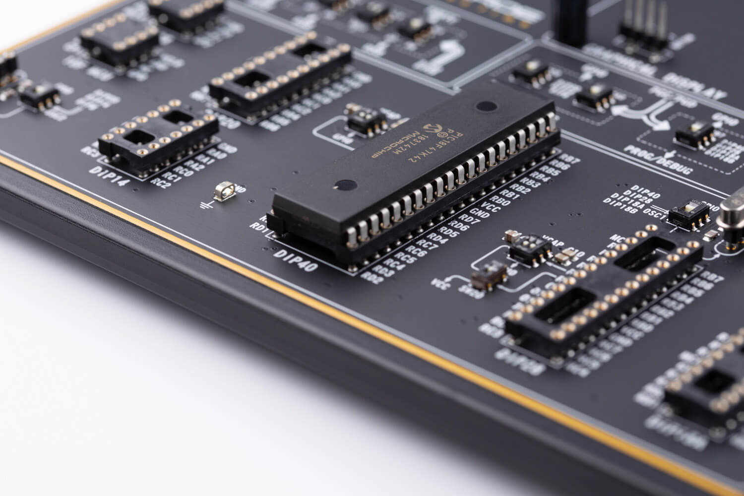
EasyPIC v8 covering a wide range of 8-bit PIC MCUs, from the smallest PIC MCU devices with only 8 pins, all the way up to 40-pin “giants”.
Board comes with PIC18F47K42 and 8MHz Crystal oscillator.

Ranging from DIP8 up to DIP40, all DIP sockets allows exclusively placement of MCUs, from the smallest to the largest one. Only a single MCU can be installed into the development board at a time.

Surface mounted technology standard enables a sturdy, compact design with improved quality of the sockets and ergonomic design, which allows comfortable project development.

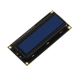
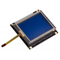
The EasyPIC v8 development board is equipped with two display connectors, one is a 1x16pin header used for connecting LCD in 4-bit mode.
The second is a single row 20-pin header, which supports monochromatic GLCD with the resolution of 128x64 pixels and EasyTFT Board capable of showing advanced graphical content.

Two display options allowing even the basic 8-bit PIC MCU devices to utilize them and display graphical or textual content.
One of them is the 2x16-character LCD module which requires minimal processing power from the host MCU for its operation. The other option is familiar GLCD based on the KS108 (or compatible) display driver, or if you want to upgrade your application EasyTFT is a perfect choice.

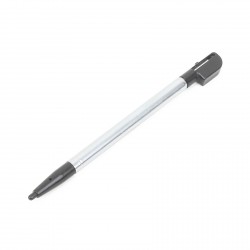
EasyPIC v8 provides the required circuitry, allowing the resistive touch panel to be interfaced with the installed MCU.
Resistive touch panel is supported over two separate connectors: one 4-pin flat cable connector (FFC) and one 1x4-pin header.
Rapid prototyping allows the engineer to take the most efficient and effortless way, to envision the design ideas, capabilities and limitations through measurable means. This is the crucial eliminating factor for time to market pressure.

The EasyPIC v8 offers five improved mikroBUS™ sockets, where you can place any of the 827 different Click boards™, adding the infinite amount of possibilities with the largest add-on-board selection in the world.

With 827 Click boards™ available, they are the fastest-growing range of add-on-boards in the world, which are standardized by pinout and size.
They enhance rapid development and accelerate time to market. These ready-to-use boards require no additional hardware configuration.
Engineered to deliver the best performances for the used components, they save developers of testing and troubleshooting often associated with the prototyping phase.

The ready-to-use Click boards™ are saving time and money by offering complete solutions of hardware and software, instead of developing them from scratch.
Choose one of hundreds of Click boards™ out of these categories: mixed signal, wireless connectivity, storage, interface, displays, human-machine interface, adapter, clock and timing, motor control, power management and audio & voice.

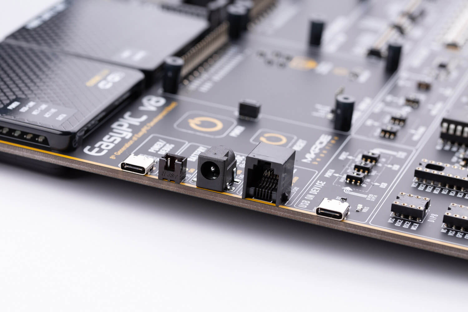
EasyPIC v8 offers state of the art power supply with constant power delivery and unprecedented flexibility. The power supply module is carefully designed to regulate, filter and distribute the power noise free.
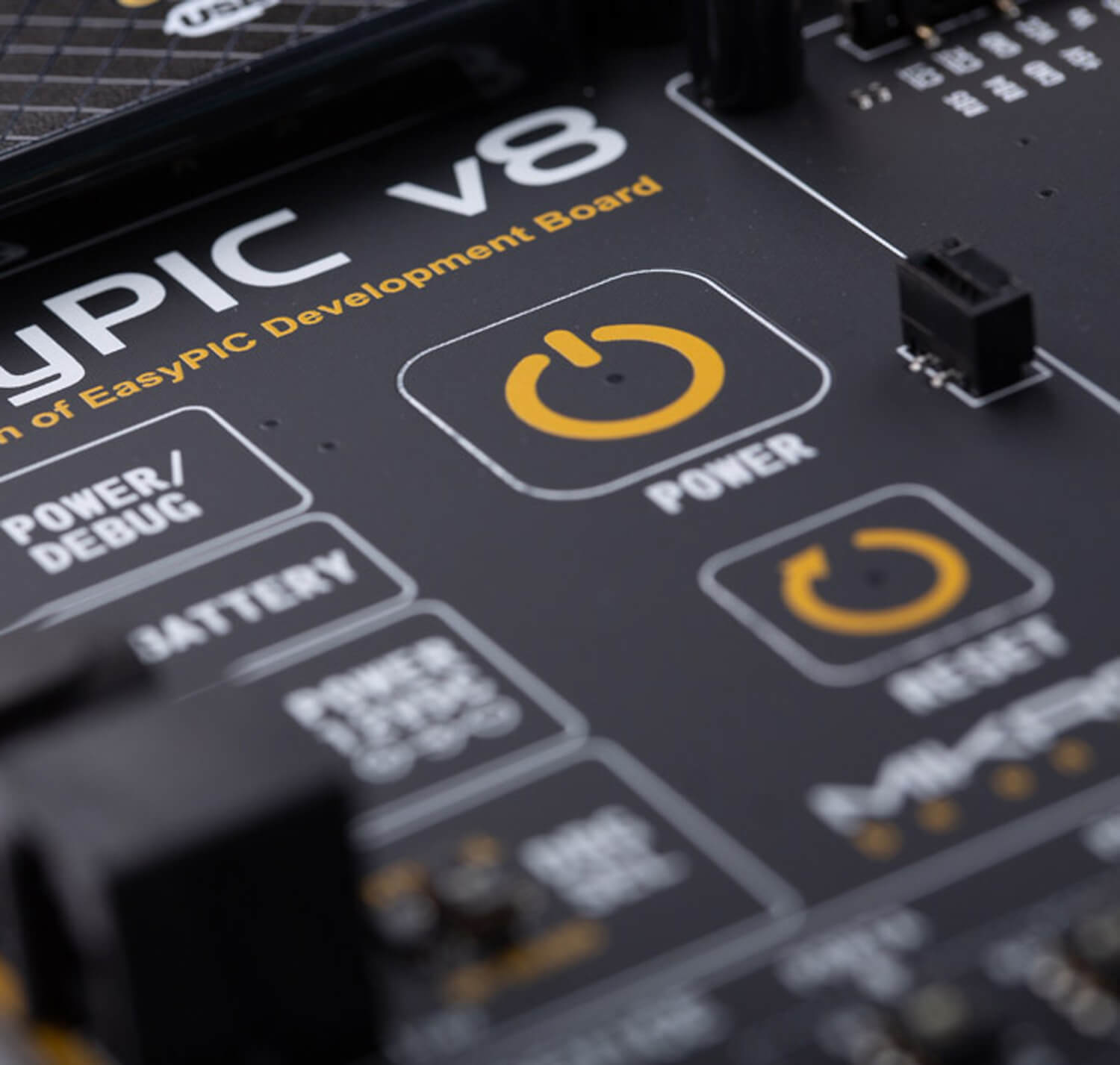
In addition, it features convenient capacitive POWER and RESET buttons.

The PSU is able to provide a very accurate, programmable voltage reference (VREF) in the range from 0V to 4.096V. It is very useful for many different applications including A/D and D/A converters, comparators, etc. The MCP4726 DAC is controlled and programmed by the CODEGRIP module, over the I2C interface. The MCP606, a single rail-to-rail operational amplifier is used to provide an additional buffering at the output.

Power supply unit supports a wide range of power sources that can be used: External 12VDC, USB-C connector, and a Li-Po/Li-ION battery.
Power OR-ing option is also supported, providing uninterrupted power supply (UPS) functionality when an external or USB power source is used in combination with the battery.

EasyPIC v8 development board offers globally unique features of 8th generation Mikroe development boards, among which the most innovative is programming & debugging over WiFi. CODEGRIP for PIC is the first ever embedded programmer & debugger over WIFI, integrated into the EasyPIC v8 development board.

You can program and debug from all over the world. With unlimited possibilities, you can place your development board in almost any hardly accessible places such as hazardous environment, agricultural settings, and high-rise buildings while still retaining full debugging and programming access.

WiFi debugging enables technical support directly to your hardware, wherever you are.
If you need the priority technical support, which encompasses consultation, problem analysis, and problem-solving visit Premium Technical Support.

The EasyPIC v8 development board is 3.2 mm thick, sturdy and durable design eliminates the board from bending when working with it. All the components of the board are produced on surface mounted technology standard, enabling a compact design.

Every detail is carefully thought through, from the height-adjustable stand with non-slip pads, to ergonomic design, which allows comfortable project development.

EasyPIC v8 features clean and elegant design, allowing the user to instantly understand how to set it up and how to easily tune it according to needs. The development board is divided into several sections, arranged so that all the related interactive components such as switches, buttons and connectors, are logically positioned and grouped together.


20%
OFF
PID: MIKROE-3614
Weight: 1900 g
OFF
PID: MIKROE-5314
Weight: 1900 g
5 10 20
Quantity discount
SAVE:
Was:
Total Save:

Secure online payments provided by 2Checkout.com, Inc.
All credit card and personal details are kept secure, and our customer
list is not disclosed to any third party.

The complete board area is divided into several sections, arranged so that all the related components, switches, buttons, indicators, and connectors are logically positioned and grouped together.

The powerful CODEGRIP module, an integrated programmer/debugger module supports a wide range of different 8-bit PIC MCUs, produced by Microchip. It allows in-place programming and debugging of all the supported MCUs, offering many useful programming/debugging options and seamless integration with the Mikroe software environment. It also offers some powerful and unique features such as the programming/debugging over WiFi; a feature that will revolutionize the way that the embedded applications are developed.
The CODEGRIP module uses the USB-C connector for a reliable and secure connection with the personal computer (host PC). The USB-C connector is also used to power the development board, simplifying the cable management.
The power supply module provides a clean, regulated voltage for the development board. PSU module supports both 3.3V and 5V power supply on a single board, this feature greatly increases the number of supported MCUs.
The PSU also contains a reliable and safe battery charging circuit, which allows a single-cell Li-Ion/Li-Po battery to be charged. When powered by the battery, it offers an ultimate degree of autonomy.
Five improved mikroBUS™ sockets, allowing interfacing with a vast amount of electronic circuits and reference designs, standardized under the Click board trademark.
Click boards™ are simple to use, require no additional hardware configuration and can be easily connected to the development board by inserting them into any of the available mikroBUS™ sockets.
A new design of the mikroBUS™ socket allows even easier interfacing with the Click board™ line of products: it has a sturdier design which helps aligning the Click board™ correctly.

The EasyPIC v8 development board is equipped with two touch-sensitive buttons labeled as POWER and RESET.
The Power button is a touch sensitive button used to power up the development board. Its sleek design and flawless responsiveness add up to the whole experience. The touch sensitive button is resistant to wear over time and it does not exhibit any bouncing effect, unlike the mechanical switches.
As soon as a valid power source is connected, the development board will enter the Stand-By mode. When the capacitive POWER button is pressed, the PSU module will start distributing the power to the rest of the development board. Below the POWER capacitive button, there is a RESET capacitive button which is not entirely power-related, but it has a similar function: it is routed to the MCU reset pin. Pressing this button will trigger a reset of the host MCU.
The EasyPIC v8 development board is equipped with two display connectors, located in the middle section of the board. One connector is a 1x16-pin header used for connecting a character-based LCD in 4-bit mode. The second display connector is a single row 20-pin header, which supports monochromatic GLCD with the resolution of 128x64 pixels and EasyTFT Board capable of showing advanced graphical content. The 1x20-pin graphical display connector is accompanied by two 4-pin connectors (1x4-pin header and 4-pin FFC connector), which are used for the touch panel connection.
The development board also provides the required circuitry, allowing the resistive touch panel to be interfaced with the installed MCU. Both the LCD and GLCD display connectors support a PWM-driven (dimmable) or fixed backlight functionality.
EasyPIC v8 features communication options such as USB-UART, USB (DEVICE) and CAN. All the connectors are positioned at the edges of the development board, so they can be easily accessed. This is also true for the power connectors, as well as for an external RJ12 ICD connector. This allows clean and clutter-free cable management.

The I/O section occupies the lower part of the development board and contains available MCU pins routed to 2x5-pin headers for easy access. There are configurable pull-up or pull-down resistors and buttons for applying logic states to MCU pins. LED indicators provide visual feedback of logic states for each pin. The MCU pins are divided into groups, following the grouping concept used on the MCU itself (PORTA, PORTB, PORTC, PORD, and PORTE). The I/O section is where the most interaction with the MCU takes place.
EasyPIC v8 development board is supported by a powerful CODEGRIP Suite, offering complete control over the EasyPIC v8 development board. It is used to intelligently manage programming and debugging tasks, and to configure various other options and settings, providing visual feedback through its clean and comprehensive Graphical User Interface (GUI). To better understand how to operate and configure EasyPIC v8 development board and its integrated CODEGRIP module, a separate manual is provided on this link.


| Type | 8th Generation |
| Architecture | PIC (8-bit) |
| Programming | USB,WiFi |
| Silicon Vendor | Microchip |
| MCU Socket | DIP |
| mikroBUS No. | 5 |
| Supply Voltage | Battery, USB,External |
| Category | 8th Generation |
$215.20
$215.20
$215.20

$6.32

$6.32

$9.92

$7.20
$7.84
$31.20

$23.20

$28.00
$1.60


Share Product
Share this product with your clients and friends.